I am not transmitting narrowband on 24GHz yet.
Ohhh ... things have advanced since that comment was made in 2007. :)
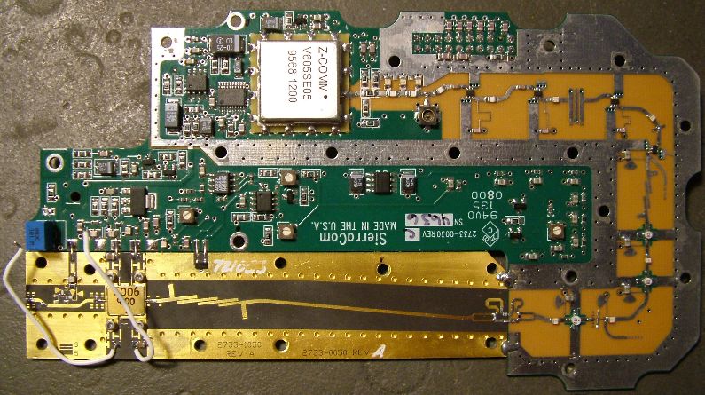
In the first half of 2010 a group of us became aware of the availability of 23 and 26 GHz Thales units being sold by an
Israeli eBayer. I managed to get in quick and get one of the 23GHz units for AU$65 landed at my door. I then discovered
this seller also had 12GHz synths, an Elcom brand of unit, so I got one of those too for a similar price. The synth had a
default freq of 12.600GHz and with that and an IF freq of 1152, I proved that the Thales unit was transmitting happily on
24.048GHz.
The availability of the Thales 23GHz gear was brought to my attention by John, G4BAO and his article
in the UK microwaves newsletter, Scatterpoint, in March 2010 and his work using these units.
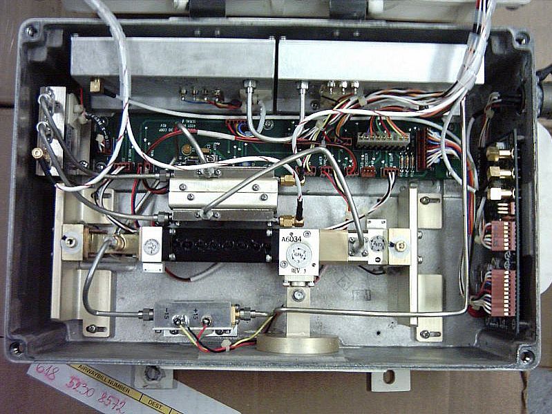
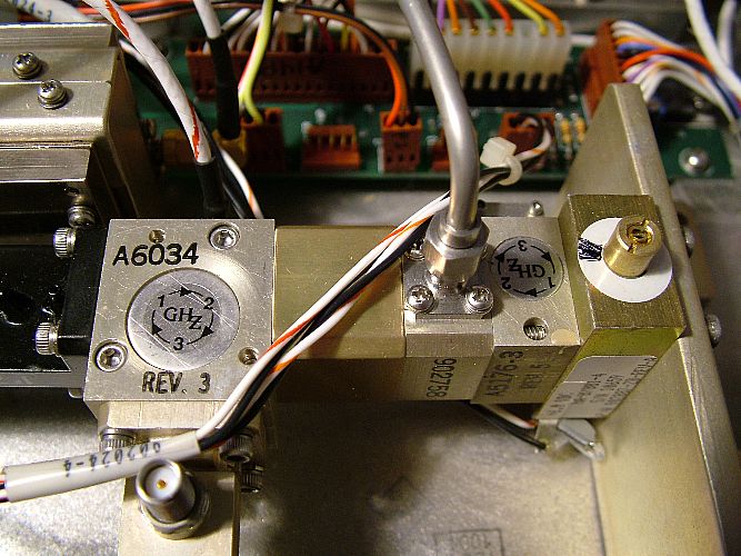
Let's look at the 2 units... click on them for larger images
Left: The Thales 23GHz unit. RX Port top left, TX top right, Centre: Elcom Synth Control Side, Right: Elcom Synth RF Side
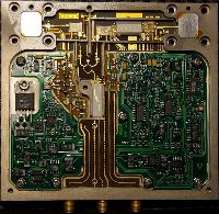
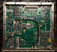
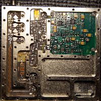
The next trick was to get the Elcom synth onto a more suitable freq. Dave, G4FRE/WW2R had already done work on the
Elcom DFS1201, a 11.2 - 12.0GHz synth. My model is the DFS1295, 12.2 - 12.95GHz. See Dave's
site for much of the details for controlling the synth from an external 12F675 PIC chip. Here is a copy of the code
I used to control my synth. I wanted a 12.670GHz LO. It can be edited in any text editor, assembled to a HEX file and uploaded to the PIC.
The next person on the scene that had played with these synths was Roger, G8CUB, He had taken Dave's code and modified it for the
DFS 1295 unit. Look here for some of his activities. Thanks Roger, your help got
me on the right path for this project.
A little bit on the synth programming that I learnt along the way. In the code noted above, these are lines that control the frequency
;values for freq 1 24048 + 1292 IF (12670MHz) ...remember to multiply frequency by 3
movlw 0x38
movwf f1_1
movlw 0x01
movwf f1_2
movlw 0x00
movwf f1_3
movlw 0x00
movwf f1_4
The synth has a default steprate of 10/3 MHz (3.333MHz). As a result some more desirable 23cm freqs are not obtainable.
I'm going to use 1.292GHz = 24.048GHz and because of the Hi Side LO freq I'm using, tuning down on 1200MHz will tune
up on 24GHz. My LO freq out of the synth will be 12.670GHz. This gets multiplied by 2 in the Thales unit to 25.34GHz minus
1.292GHz = 24.048GHz.
The synth has a x3 multiplier in it so the freq programmed into our controller PIC must be x3, therefore operating freq 12.670 x 3 = 38.01.
in the first 2 sets of "movlw" lines above you can see where the 38.01 has been inserted. A second freq can be prog'ed in and
this can be selected with the Jumper 1 pin on the circuit board, say for a 432MHz IF etc.
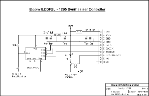
The circuit for the synth controller is based on the circuit from Dave, G4FRE/WW2R but with some differences. Notably the DFS1295 runs off +8 and +12V. Dave says the DFS1201 (which is basically the same unit, different freq range) has +6 and +12V rails. I cant confirm that I haven't seen one. Dave's site noted above, has the circuit he used for the DFS1201. Heatsink the 8V regulator, it does get quite warm, drawing ~ 270mA. The 12V rail draws ~ 120mA.
Click for larger image
9 May 2010 Update
With some holiday time off work I have had time to do work on several projects including the 24GHz Xverter.
Below is a layout drawing and an image of the current progress on the system. Both the drawing and image will be updated as the project progresses. Tonite I will finish adding the TX IF to relay cable and start to plan the various PSU rails needed. I placed a smear of heatsink compound between the Thales transceiver unit and the case. I have yet to decide if I will add finned heatsinks to the underside of the case. That will prob. be determined during testing when I feel how hot the case gets during extended use.
12 May Update
The project continues to advance. Over the last few days I have been workng on the system layout (latest update below) with maybe a few additions to go yet, but its close to finished. The actual construction is also progressing with the arrival of a suitable PSU. Jack VK2TRF alerted me ( that Dan, VK2GG obtained) to a 12VDC input DC-DC converter PSU board designed for running an ATX computer M-brd. In Australia these are available from Jaycar for AU$99.00 (at the time of writing this). Its' outputs are +12V @ 12A, -12V @ 100mA, (just enough for the Thales unit) +5V @ 6A and +3.3V @ 6A. The top cover of the case has been drilled and standoff mounted for the PSU board. Two rectangular holes have also been cut out for the 2 sections of flexible WG to exit the case.
Initially I am going to drive this transverter with the 1292MHz output from my Alinco tri-band handheld. Low power setting on it is 300mW,
+24.8dBm and that needs to be substantially attenuated to around -10 to 0dBm. I have cut out a nice fixed attenuator from a bit of commercial
commercial gear, a RFP 25-20AP and its assoc bit of PCB and additional Pii resistor attenuator pad. The RFP 25-20 is a screw mounted
25W, 20dB attenuator and will more than handle the 300mW going into it. There is also a 5dB attenuator between the Elcom Synth and the Thales unit. Only +8 to +10dBm max. LO drive is needed and the synth is producing a solid +14dBm out. The "Lock Detect" LED on the side
of the case will be a high intensity LED, prob blue, so as to be easily seen in bright sunlight.
OK that will do for now :)
14 - 16 May Updates
A few more updates to the drawing. Also over the last 2 days, I have done some serious work on the transverter, installing the RFP25-20 attenuator board and the cabling between it, the relay and the Thales unit. Added 3 hi intensity LED's on the front panel. Initially, I was only
going to have a Lock Detect LED but decided to add LED's for PWR on and TX as well. Also added was the coax cable between the 5dB
attenuator between the synth and the LO input to the Thales. I ran the +12VDC line from the synth driver board around the inside edge of the case.
Click on the pix below for updated images
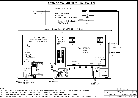
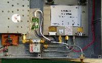
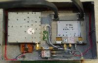
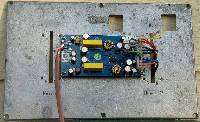
Left - Layout Drawing; Cntr Left - Cabling Area Closeup; Cntr Right - Full view; Right - ATX PSU Mounted On Case Lid
Note .... Ignore the text on the lid in the PSU pic, the remains of the cases' former life. Will probably be painted over. The 2 rectangular slots
either side of the PSU board were already there too. One of, as can be seen, will be used for power cable entry. The two square'ish hole in
the top right area I have cut for the TX and RX flexible waveguide entry.
16 June Update
Waahooo :) well after a couple of weeks of no posts, during which time I have been busy. I can now announce the arrival of a new 24GHz
transverter. It is now finished and ready to try out when I have some one to talk to, come on Dan and Jack ;) Actually Dan, VK2GG, is probably
the first one I will get to talk to as his xverter is the closest to completion.
Below are a series of pix showing outside and inside views (Click on them for larger images)
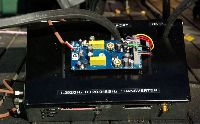
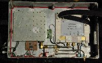
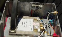
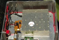
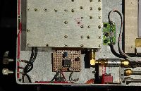
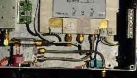
You will notice in the lower left and centre pix, 2 black cables coming out of the left corner of the Elcom Synth unit. It was a last minute
decision to tap into the internal 10MHz reference line and extend it to the connectors on the case. A patch lead between these 2 connectors allows the internal 10MHz ref. to be functional. For better stability, the patch can be removed and an external 10MHz ref., eg. a Rubidium Standard or a GPS disciplined oscillator can be injected into the Ref In connector.
I have found the internal ref. to be a bit unstable, after initial warmup, it still wavers several 100 Hz. This is no problem for NBFM use, but would
be a pain on SSB. Experimenting with my Trimble GPS-DO (I got from a well known Chinese ebay seller) I found even without the GPS antenna
connected, the 10MHz is very stable. The GPS ref takes ~ 2 minutes to stabilise. Below is a pic of the Trimble Thunderbolt unit.
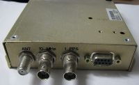
I intend to use this for my 10Ghz system in the field as well. It will replace the basic 10MHz ref currently being used which unfortunately has an
annoying ~ 900-1000Hz tone that gets superimposed on my signal. It totally distorts a SSB signal making it unreadable. The 10MHz rubidium standard will get used in the shack for referencing the spectrum analyser, sig gene and freq counter.
11 July Update
The, hopefully, last couple of mod's.
Mod 1... I have replaced the Mini-circuits 5dB attenuator between the Elcom synth and the Thales xceiver with a HP8493A 3dB attenuator.
The miniccts one was only rated to 4GHz and at 12GHz its attenuation was over 10dB and resulted in a too lower level of LO drive. It took the ~ 25mW down to ~ 4mW. The HP 3dB atten. (rated to 12.4GHz) took the level down to 11mW.
Mod 2... Was to mount the Trimble Thunderbolt unit inside the transverter case, rather than strapping it to the outside. With the 4 connectors from it protruding from the rear wall of the case, they are easy to access. Specially with just a short run of coax from the 10MHz output around the side of the case to the 10MHz in to the synth.
This has been a really enjoyable project, really pushing my boundaries of construction and dealing with new and much higher freq technology.
I hope others that read this project write up can take parts of it and apply it to their own 24GHz transverter construction.
 Back to amateur page