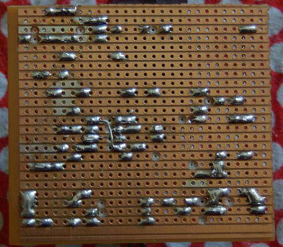
This circuit couldnt get much simpler. As show in the pic of the transmitter on the previous page, it is built on veroboard.
The 500 Ohm tuning variable resistor is a 10 turn pot, so as to get fine enough adjustment.
The circuit is partly based on ideas from Ham Radio magazine, 10 gig project; Jan 1979.
The basic principle is to provide a stable DC supply to the Gunn Diode and then modulate that supply with the voice or tone signal,
this produces a FM signal that is around 150kc in bandwidth, ie. WBFM

Although I have the switch for the tone generator mounted on the cct board as a small pushbutton type, it would normally
be a small toggle switch mounted on the back panel of the case
12 Dec. 2008 update...
NOTE: Whilst helping to build a board for VK2CQ, I noticed a mistake in my component placement on my board
There is an 8k2 resistor from pin 8 of the 555 timer on an angle to the track above. It should be between pin 7 and
pin 8 of the 555 timer. The cct diag. is correct.
When I get time I will re-photo the cct board showing the corrections.

With the top of the component side flipped towards you, ie. no horizontal rotation, the trackside should be a mirror of the component side.
Page Created 27 Feb. 2005; Updated 12 Dec, 2008 Dave Nelson